No products in the cart

Calibrating Gen 1.3 Misting Unit for Small Nozzle Circuits
Small nozzle circuits containing less than 20 nozzles will often cause erroneous errors to appear on a Gen 1.3 System. The root cause of the issue is the flowmeter (“Gen 1.3 Leak Detection Kit”) used to check for possible nozzle circuit leaks by measuring the output flow rate of the misting unit. Per the manufacturer, the operating window of the sensor in the flow meter begins at a flow rate of ~ 800 mL/min. Years ago, we determined experimentally that the average flow rate of slimline nozzles is ~ 40 mL/min, so to reach the operating window of the flow meter a nozzle circuit must contain at least 20 nozzles.
However, in cases where it’s not possible to install a nozzle circuit that has 20 nozzles, we can make a few minor adjustments to the misting unit to reach the operating window of the flow meter. To do this, we will install a second auto-drain valve (SKU 10427) onto the internal plumbing of the unit, this time downstream of the flow meter. Because the auto-drain valve outputs about 40 nozzles worth of fluid on its own, it will allow us to easily enter the operating window of the flow meter.
Retrofitting the Gen 1.3 Misting Unit:
- Remove the tubing connecting the pump outlet fitting to the agitation valve inlet tee, per image 1
- Cut a ~12-inch piece of 1/4″ tubing
- Push one end into the pump outlet fitting, per image 2
- Leave the open end of the agitation valve inlet tee unconnected for now
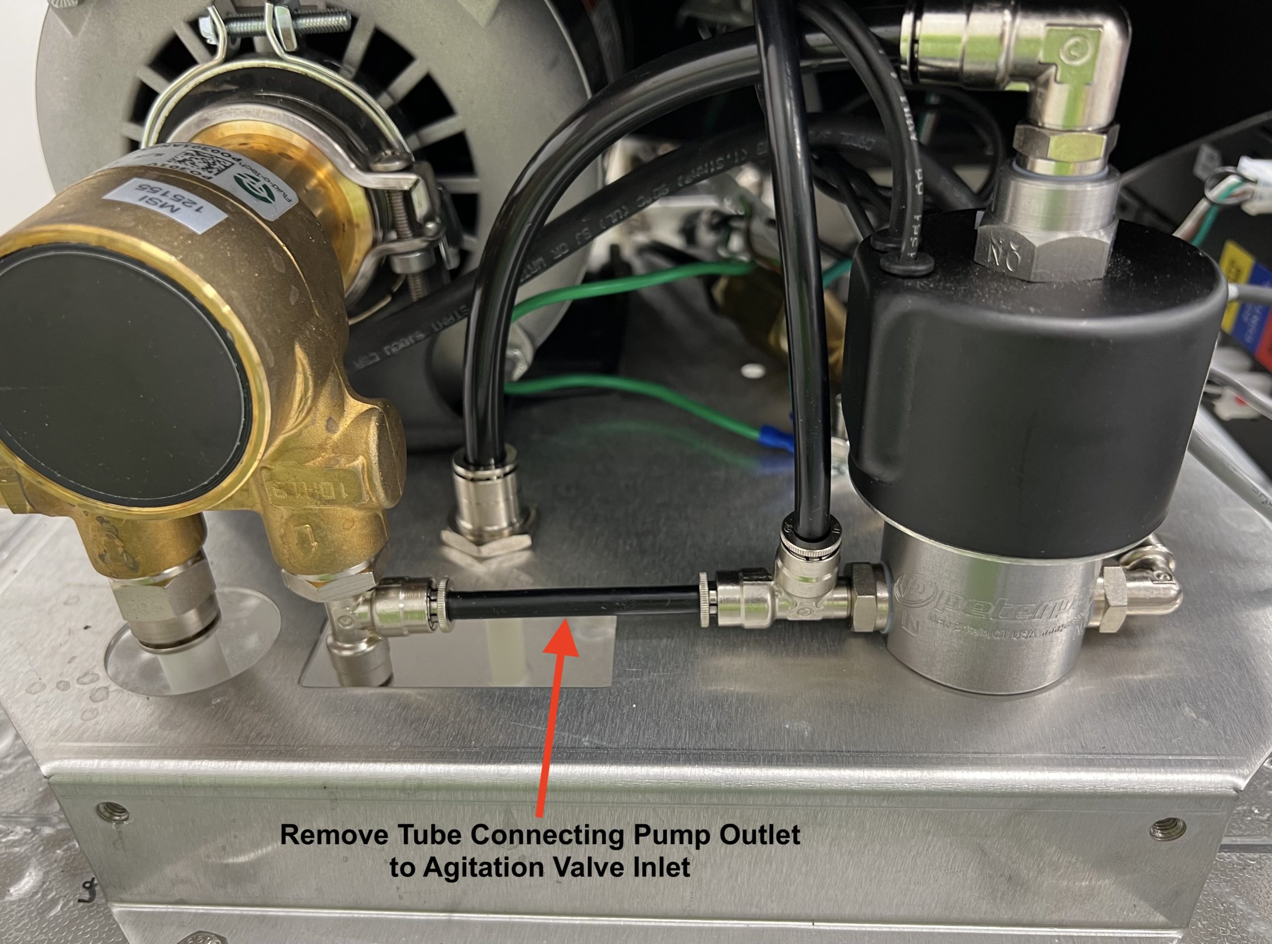
Image 1: Normal Gen 1.3 Pump/Valve Connections
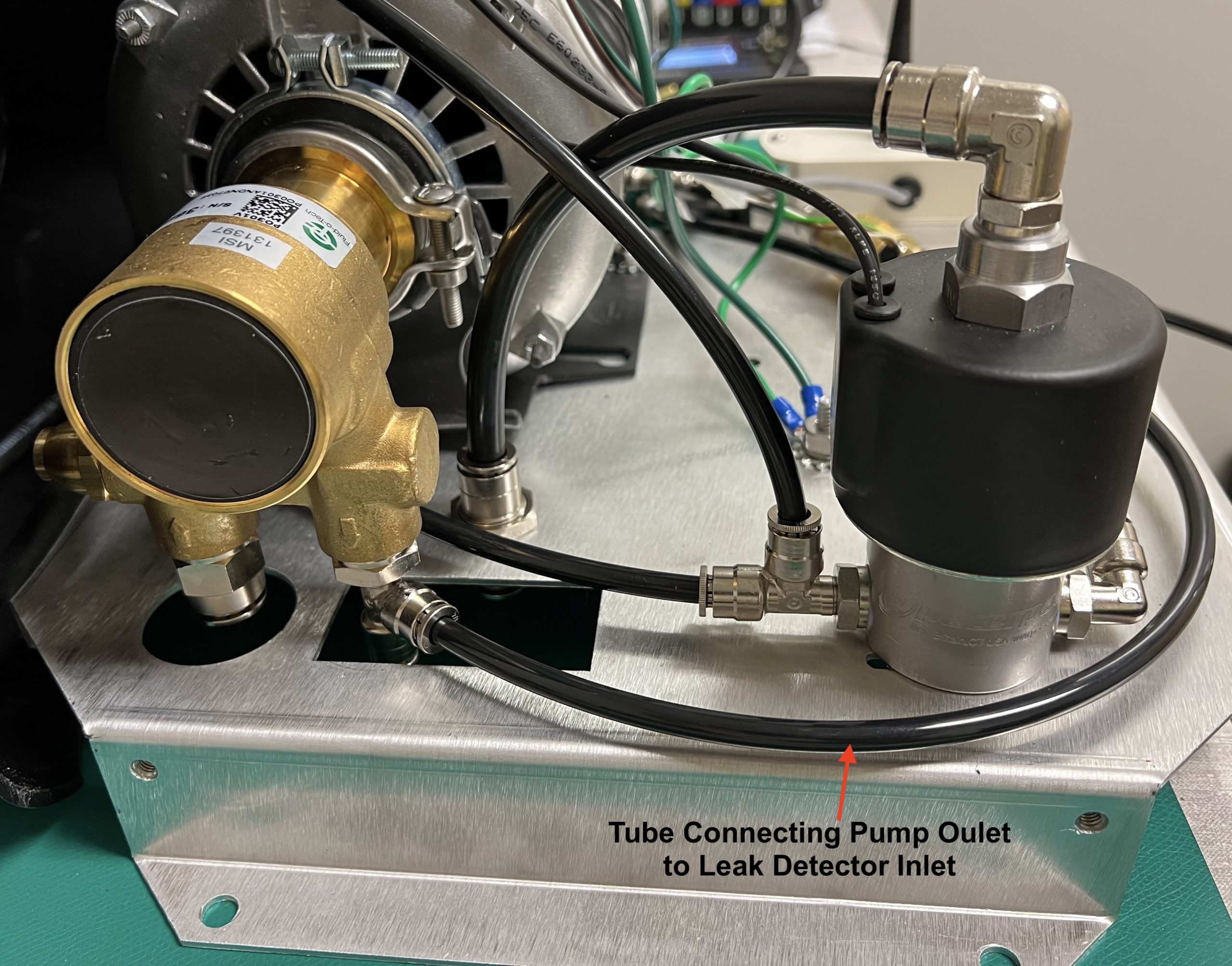
Image 2: Retrofitted Pump Connections
- Disconnect the tubing on either side of the flow meter.
- Curve the 1/4″ tubing connected to the pump outlet around the agitation valve
- Insert the free end into the inlet fitting of the flow meter, per image 3
- Cut a 2.5-inch piece of 1/4″ tubing
- Insert one end into the outlet fitting of the flow meter
- Push the other end into a 1/4″ union tee
- Drill a 3/8″ hole through the lid directly underneath where the union tee is located
- Feed a 2-foot-long piece of 1/4″ tubing through the hole and attach an end to the union tee, per image 4
- Attach the second auto-drain valve to the other end of the tube (inside the tank)
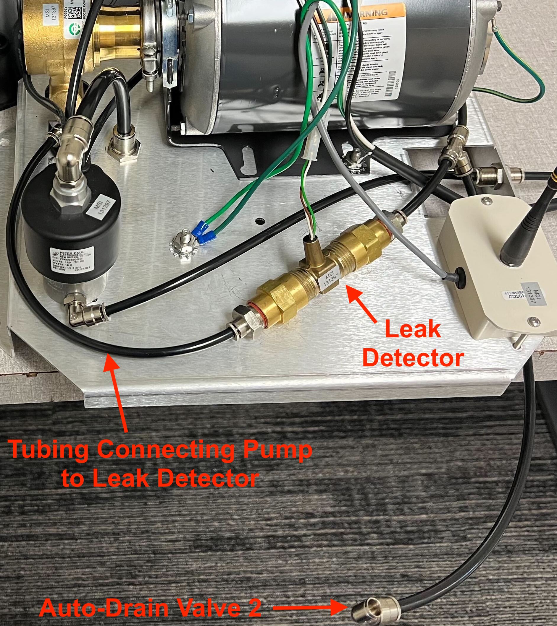
Image 3: New Flowmeter Connections
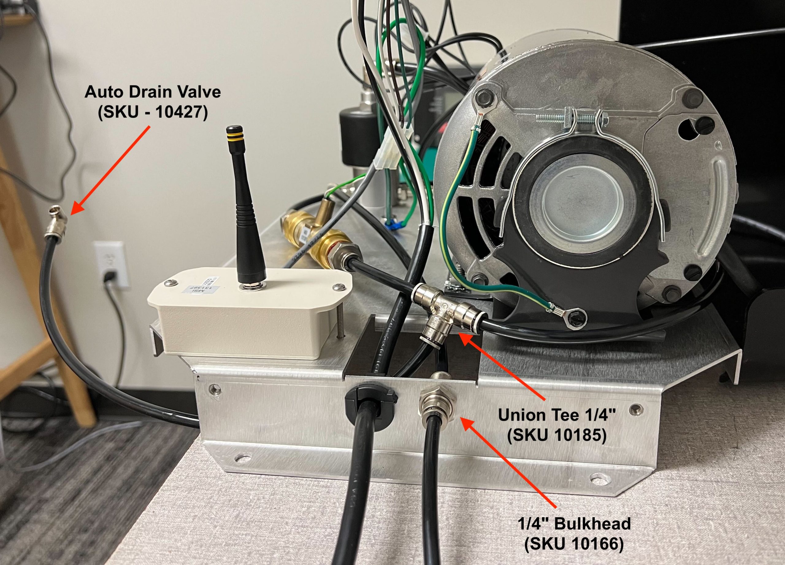
Image 4: Plumbing Second Auto Drain Valve
- Attach another piece of 1/4″ tubing to the remaining open end of the union tee
- Wrap this tube around the backside of the motor, per image 5
- Insert tube into open end of the agitation valve inlet tee
- Finally, connect a piece of 1/4″ tubing between the agitation valve’s outlet fitting and the 1/4″ bulkhead on the side of the chassis
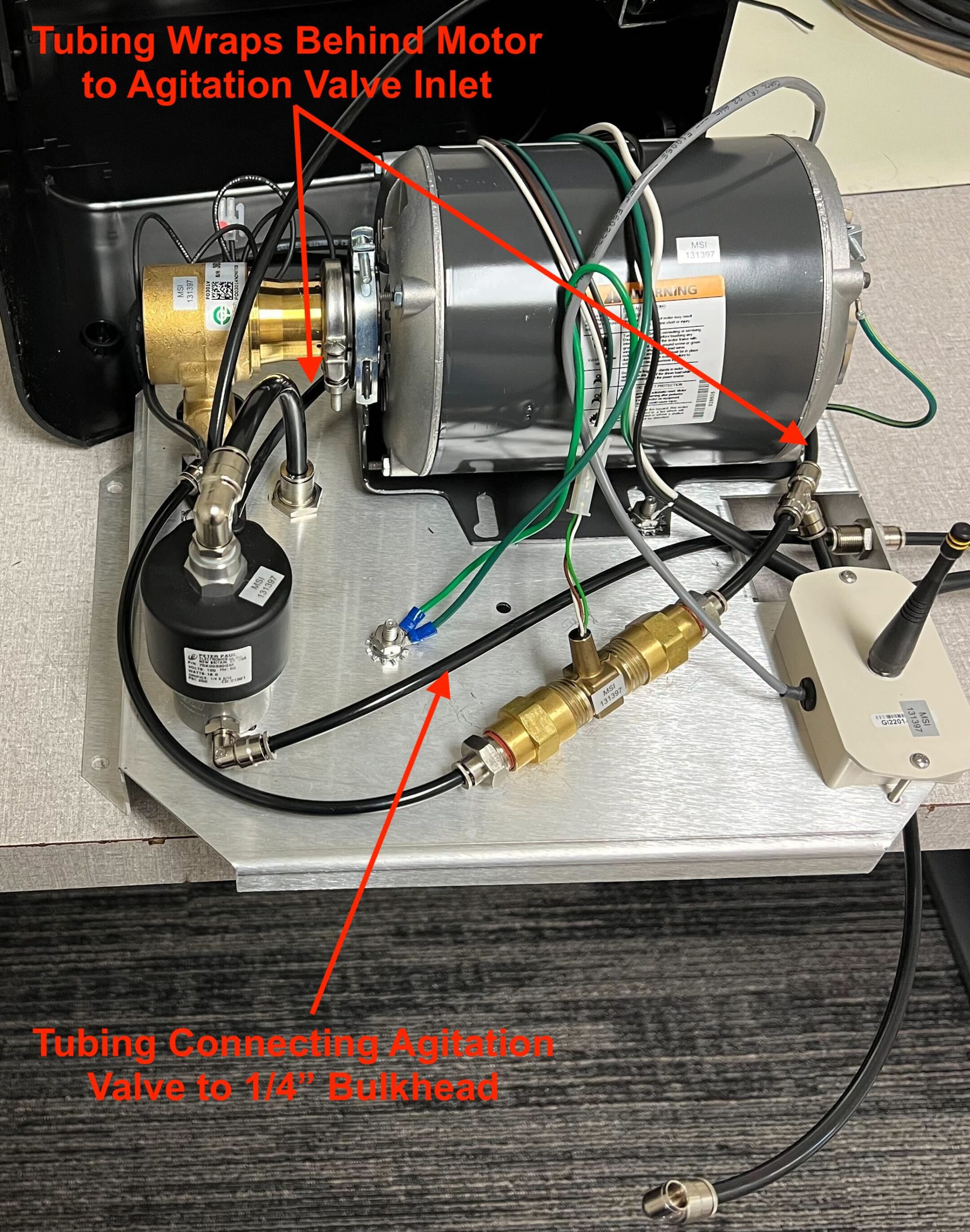
Image 5: Gen 1.3 Retrofitted
Calibrating the Controller:
Step 1: Programming Controller’s Nozzle Count:
You will need to increase the nozzle count (Setup menu -> “NOZ”) in the controller by 40 to account for the extra auto drain valve that we’ve added. So, for example, if you have 12 nozzles at the customers home, you would input 52 nozzles into the controller’s nozzle count. This will account for the extra flow rate of the second auto drain valve to give accurate flow rate readings.
Step 2: Programming Controller’s Tank Volume
Next, we will need to adjust the tank volume to account for the “extra” volume that the controller thinks it’s misting during each mist cycle, even though only 12 nozzles are actually misting. To do this, adjust the “Tnk” setting in the Setup menu of the controller by using the following formula:

Where:
- Tnk (total) = The adjusted Tnk volume that must be input into the controller
- Volume (actual) = The actual volume of the tank = 55 gallons
- Nozzle Count (A.D.V.) = Auto-drain valve = 40 nozzles
- Nozzle Count = The actual # of nozzles in the nozzle circuit
Simplifying the formula further, you get:

Example: For a nozzle circuit that has 12 nozzles, the formula will look like this:
