No products in the cart

Gen 3: Replace Gray Plastic Flow Meter
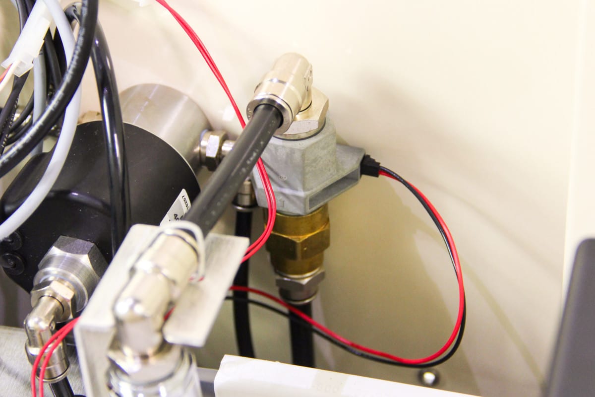
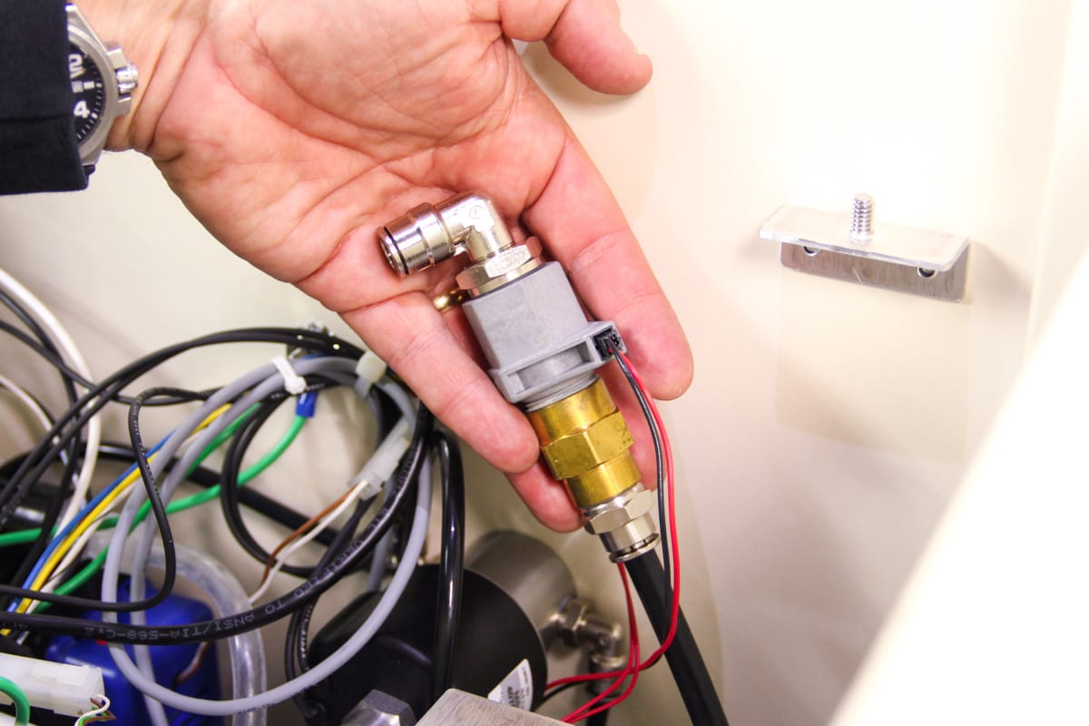
The flow meter is the gray component with the red and black leads located against the back right wall of the unit. This component was used in Gen 3 units sold from 2007 – 2011. It is no longer available and must be replaced with a brass flow meter. This also requires replacing both the controller and the wiring harness in the unit.
To make the replacement, you will need to purchase a new MistAway Gen 3 controller along with a new brass flow meter and wiring harness.
Time: 20 minutes
Tools: zip tie snip
Parts:
- Gen 3 Controller (#11420)
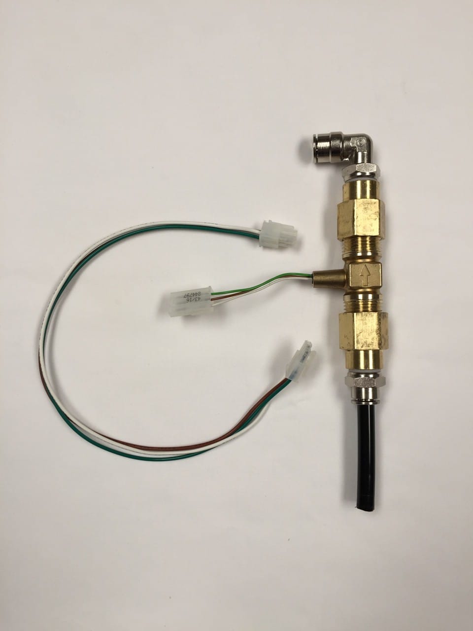
- Brass flow meter assembly (#10986)
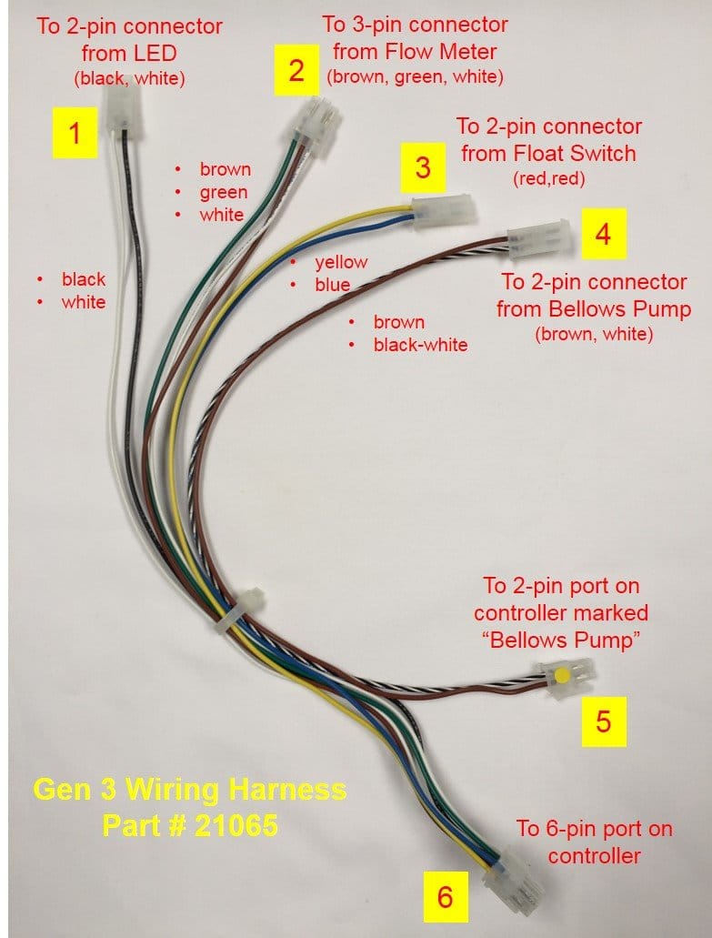
- Gen 3 wiring harness (#21065)
1. Remove the existing controller
A. Note controller settings on your controller (nozzle count, remote and auto misting cycles and durations), these will be used later to set up the new controller
B. Remove controller from well in shroud and disconnect controller from the wiring harness, power and motor cables.
C. The old controller is now obsolete and should be recycled.
2. Remove gray plastic flow meter and install brass flow meter
A. Remove screws securing shroud. Rotate counter clockwise and hang shroud from left side of the unit. See Gen 3: Access Components by Repositioning Shroud.
B. Cut zip tie securing wiring harness on back wall.
C. Remove connector (red and black wires) from plastic flow meter
D. Disconnect and remove plastic flow meter (including 3/8″ tubing that connects it to the water inlet valve at base of unit)
E. Connect brass flow meter (using included 3/8″ tubing) at base and top. Discard included pigtail (brown, green, white wires connecting 3-pin and 4-pin connectors)
3. Replace wiring harness
A. Disconnect existing wiring harness from components (LED, float switch, bellows pump).
B. Connect new wiring harness to components as pictured.
C. Anchor new harness (and black leads from agitation and inlet valves) to mount on back wall with zip tie (and snip).
4. Connect new controller
A. Return shroud to original position. Make all connections to back of the new controller (6-pin, Bellows Pump, Water Inlet, Agitate Valve, remote cable, motor, power, iMist)
B. Program settings that you noted in step 1A.
C. Run a couple of remote or manual mists to ensure unit is functioning properly.
D. Secure controller into shroud with thumb screws.